Minor issues with control valve operation can have a significant impact on the operation of the entire system if they are not resolved in a timely manner. Because control valves are referred to as the muscles of the processing system, these parts must operate more swiftly and precisely throughout the day.
Control valves are mechanical devices, but despite this, they operate poorly and lose efficiency with time. Whether you have a brand-new valve in your system or an old manual one, it is important to track and maintain the performance of the control valve and follow the control valve maintenance procedure. While occasionally the flaws can be quickly detected by a skilled eye. In today’s blog, we are going to describe control valve troubleshooting and provide the control valve troubleshooting guide.
Common Control Valve Problems And How to Fix
Does Leakage Tolerance Exceed
Introduction
In a dead band, the control valve system is essentially dead because there is no output for any input. A dead band generally happens when the valves need to shift the direction from sources—either purposefully or unintentionally.
The Dead band divided by the modification in controller output rate represents an increase in loop deadtime. An increase in dead time might result in a load disturbance with higher peak and integrated errors. Due to the integrated action of the valve positioner, the system will develop uneven controller speed or processor cycle constraints if there are two or more integrators present.
Symptom & Indication
These are indications that a band is dead when the controller signals are unable to find or activate any valve action. The control valve responds to backlash between the controller output and valve position in the case of a dead band.
1.more errors caused by load disruption.
2.increase in system idle time
3.Control loop that fluctuates frequently.
4.erratic control.
How to Fix
Before the valve actually moves, the dead band must be stretched across when the controller output changes direction. A Dead band can be helpful in some circumstances, but its repercussions are usually terrible.
The best course of action for the control valve is to thoroughly remove the Dead band. An increase in PID (proportional integral derivative) gain can reduce the Integrated Absolute Error by raising the rate of change of PID, hence reducing the decrease deadtime owing to the Dead band when you are trapped with the Dead band principle in a large valve source.
The problem in practice is that the dead band can vary depending on valve position, operating circumstances, and positioner tuning time; the effect of output following a direction shift eliminates the deadtime and losing of movement from the backlash.
How to Avoid
In addition to mechanical backlashes that result from loosening or mechanical linkage, other factors such as excessive valve friction, a malfunctioning positioner, or shrinkage in the size of the actuator can also result in a Dead band.
When utilized in series with the throttle valve, isolation or on-off valve offers a significant advantage. For some upstream and downstream runs, when control valve maintenance is required to be minimal but can result in a more stable flow relationship between the valve position, the throttle valve is positioned in a more accessible location for easier maintenance.
In open-loop step testing, the increased deadtime of the Dead band is not discernible, but the process of changing the step change’s direction is sped up. A simple algorithm can be set up to modify slightly less than the Dead band, where the output switches direction with a larger noise band visible in the PID output, to upfill the change in PID output.
Stiction
Introduction
The term “stiction,” which combines the words “stick” and “friction,” is another frequent problem with control valve loops. This phrase describes a situation that fixes the valve in place, preventing it from moving like a Dead band. The valve requires more force to move when there is stiction, which can also cause it to exceed its position and its process setpoint, such as the Dead band, causing it to become stuck in an unexpected or incorrect position.
Stiction is frequently observed in control loops running in pre-set mode, manifesting as a continuous cycle pattern in controller output and a square wave pattern in process variables, leading to process disruption and valve tears.
Symptom & Indication
A stiction issue exists if the CO is shown to shift more than 0.5 percent per cycle.
- Internals of the valve can be stuck.
- miniature actuators’
- media elasticity
- Tight Turn Off
- Never will the control valve reach the proper set point in stiction.
- The valve continues to adhere to a new position.
- The process operates in the opposite way as a result of the controller’s output, which reverses the direction.
- Stiction causes a loop cycle; the output movement of the control valve will resemble a saw-tooth wave, whereas the process may resemble a square wave or irregular sine wave.
How to Fix
The valve actuator and positioner must be properly adjusted to change the force necessary to move the valve in order to address issues with stiction in the valve. determining whether the valve’s air pressure is within the range specified by the control valve’s manufacturer by performing a torque check on the valve packing gland. Additionally, it is advised to visually examine the valve’s internals for indications of scaling, scarring, or general wear and tear, and replace the valve as necessary.
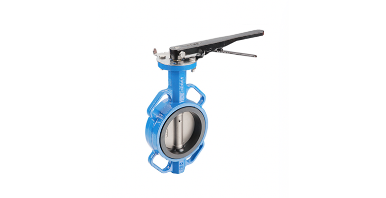
Locating the valve, confirming that it is oriented correctly, and determining whether it is less susceptible to stickiness as a replacement alternative for high-performance butterfly valves can help reduce the problem of stiction that is exacerbated by using viscous or sticky process fluid.
How to Avoid
A few issues that need to be fixed in order to prevent frequent valve sticking are what cause the stiction or binding problem in valves. Stiction is primarily caused by packing that is either too tight or damaged; this packing needs to be replaced with a new set, and the flange of the packing needs to be tightened until hand tight and with just one turn of the spanner.
Regularly check to see if it is straight; any marks or rough areas can be found by running your palm over the entire surface. The valve should be properly cleaned, smoothed with fine grinding paste, and installed if there are any suspected areas of uneven alterations.
Positioner Overshoot
Introduction
Position overshoot has been identified as another issue in recent years that is more prevalent. These positioners are quick feedback controllers that measure the position of the valve stem and adjust the valve actuator to move the valve to the desired position. The majority of valve positioners can be tuned, but when it comes to the controlling valves they are tuned too aggressively, which causes the valve to overshoot its position when the controller output changes.
Sometimes the overshooting is just the result of a positioner defect. If the process controller is aggressively tuned as well, it interacts with the valve positioner to generate positioner overshoot, which results in significant loop fluctuation.
Symptom & Indication
There may be screw repositions, weakening parts like springs and mechanical linkage, and the control valve positioners may have been stroked repeatedly throughout use. These valve positioners are subjected to several valve seatings and liquid or gas passages.
Valve positioners typically enable tighter process control, however, a damaged positioner will overshoot without keeping the precise speed and failing to reach the valve’s set point. Additionally, these positioners will exhibit reduced friction and influence performance; components suffer from calibration drift, leading the valves and positioners to work with incorrect regulations from glasses and liquids and function prematurely with requirements.
How to Fix
Setting a short integration period will eliminate the offset caused by the integral time acting as an error later in the control valve. Overshooting of the positioner can be controlled by modifying the integral, percentage, and derivative settings. To remove the offset, practice gradually raising the integral time value until the fluctuation is apparent.
In some applications, the derivative time acts as a decelerator for managing the loop, while in others, control valve applications, a tiny overshoot is acceptable. The derivative control may be able to lessen overshoots in specific circumstances. However, it may result in a lack of the desired responsiveness that is required to make the best use of the derivative time.
How to Avoid
It is advised to only make one adjustment at a time because making many changes could throw you off balance and changing the valve position could move the positioner. Proportional gain regulates how rapidly a process races to the setpoint; a high gain setting might hasten the process’s arrival at the setpoint but will cause a significant overshoot and positioner fluctuations. Although it could take longer to reach the setpoint, a low gain may prevent an overrun.
Set the integral, derivative, and proportional times to zero initially as a precaution to prevent overshoot. Then, gradually increase the proportional gain value in small increments until oscillation occurs, and then decrease the setting.
Incorrect Valve Sizing
Introduction
Incorrect sizing or oversized valves are additional issues with control valves. Particularly in smaller-sized valves, these missized valves might exacerbate the issues. In accordance with the characteristics, curves, and operating circumstances of the valves, the valves should be the correct size to acquire the travel flow precisely.
Even a small change in valve position can have a significant impact on flow with an oversized control valve, and bottlenecking can happen with an undersized control valve. Sometimes control valves are greater in size than the flow rate they are intended to control, which causes the valve to operate with a tiny opening even when the flow is at its maximum.
Symptom & Indication
The control valve is enormous if it needs to open and close frequently, making it unstable. Despite the valve’s repeated attempts to achieve your chosen setpoint, its sizing problem prevents it from precisely achieving the desired flow of pressure at the setpoint.
Another sign of a controllable sizing issue is water hammering, which can happen in gas or oil applications. This may cause the valve to close abruptly, stretching the valve stem and eventually compromising it. The coupling block and valve seat may get so stressed from water hammering over time that they will fail.
The poorly sized valve can also result in a high stroke count, which accelerates the valve’s aging process over time relative to what is expected under typical working conditions.
How to Fix
Poor control performance can occur from incorrect valve sizing due to valve positioning mistakes, such as stiction and dead band, which are caused by large valves. Sizing issues can also be resolved by making a few adjustments to the output, either by manually regulating it or by automatically managing setpoint modifications. Process adjustments should be made at least twice, with greater changes being preferable.
For usage in control loops where the process again reduces and the flow rate raises periodically, an adequate portion of the control valve should be optimized when the pressure across the valve decreases as the flow rate increases.
How to Avoid
To maintain the safety factor on both ends, it is always ideal to have a minimum opening of up to 20% and a maximum opening of up to 80%. If a set of tuning parameters only affects one end of the control range and not the other, the flow characteristic is erroneous.
High-performance butterfly valves, segment-ball control valves, and full-ball valves are frequently two sizes smaller than the actual line. A substantial change in inflow can result from even the slightest adjustments made to the valve’s location. Because an oversized valve is so sensitive to operating circumstances, it might be challenging or even impossible for the valve to precisely adjust to the required flow.
Nonlinear Flow Characteristic
Introduction
Control valves are made with a linear flow in mind. Consequently, a non-linear flow also causes tuning issues. As a result, non-linearity may result from any of the aforementioned factors, such as positioner overshoot, dead band, stiction, and inappropriate size. The relationship between flow rate and valve position under typical operating conditions—which is expected to be linear—is the flow characteristic of the control valve.
As the valve position may vary away from its operating point, a nonlinear feature can only offer the best controller response at the operating point; otherwise, the loop may become completely uncontrollable or static.
Symptom & Indication
At the first symptom of issue, nonlinear flow in the control valve begins to manifest itself; as difficulties worsen, this valve will start vibrating and begin to dislodge certain internal components. Reverse flow and severe component wear and tear are visible. These valves make noises, commonly referred to as “water pounding,” when they degrade as a result of nonlinear flow.
Such water hammering disrupts the flow and causes the disc to crash onto the valve seat. resulting in pipeline ruptures and significant harm. As valves degrade, damage to the flow characteristic also gradually contributes to sticking and valve leakage.
How to Fix
The most crucial steps in fixing control valve problems are to make sure the valves are operated as intended; each valve needs to be installed and maintained appropriately. The concentric butterfly valves perform more effectively when the correct valve is chosen for the specified purpose.
In order to ensure optimal functioning and safety, it is also important to replace the valves as soon as symptoms of wear and tear appear. Failing to do so could result in a system failure.
How to Avoid
Keep these valves clean as preventive measures to avoid defective valves and serious damages. Contaminants and debris may cause blockages and leaks that result in valve failure and nonlinear flow; keeping the pipes clean is the simplest and most efficient way to avoid any harm.
Where necessary, the installation of filters and coverings can prevent debris from entering the system. The liquid systems and pumps should be flushed frequently to keep the system clean.
Use the proper lubrication for valves on a regular basis to improve performance and ensure smooth operations. Regular lubrication also lengthens the lifespan of the valves and the system they are operating in.
Control Valves Inspection And Maintenance Guide
Examining The Control Valve On A Regular Basis
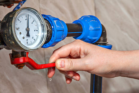
Your control valves should be physically checked on a regular basis; ideally, this should be done once every 12 weeks, but this depends on how well the machine is working. By focusing on tube leaks rather than pressure gauges, this check ensures that the valve is functioning as it should. Regular inspections can also pick up on any irregularities or inconsistencies.
Make sure you have the instruction manual handy when performing any fixes if any are necessary. On their websites, the majority of manufacturers make their manuals accessible online.
Ball Valves Are Turned Off By The Pilot System
The main control valve’s three isolating cocks are useful. Three are located on the valve: one on the top of the valve on the bonnet, one on the upper stream side of the valve in front of the filter, and one on the lower side of the valve below the pressure-reduction pilot.
When the handle of the isolating cock is in line with its body, it can be released by first giving the cock a brief turn in the closing direction and then turning it back to the opening position.
Air Blockage
The main culprit for giving a misleading measurement of the pressure in the control valve and impairing the valve’s performance is air existing in the pilot system. With a control valve that has a position indicator, release air from the valve bonnet. The air bleeding cock is located on top of the position indicator. Turning the bleed cock in the other direction from clockwise permits air to escape.
Run the water until the air is released; if there is air present, the water will be frothy white. The high point is another exit to bleed out the air from the valve. Shut the cock if the water is clear and flowing and there are no air bubbles visible in the position indication glass.
Get The Strainers Clean
The water supply from the valve’s inlet is primarily what the pilot systems with built-in control valves rely on. Therefore, for this reason, external strainers or flush clean type filters might be used. For an external filter to clean its screens, a typical 3 to 5 second flush is all that is required. It will suffice to have some practical experience to comprehend how long exterior valves must flush.
For a routine, brief flush every time the valve stations are opened, a ball-type valve is often mounted on the flushing plug of the filter in most applications. By following these routine procedures, the valve strainer is kept clear of clogged strainers, which prevent the valve from closing.
Pilot Decrease
It is simple to check the pilot functioning condition of the control valve. The system and SCADA alarm controls that cause a pressure influence should accept any adjustments you make to the pressure. Release the lock nut on the pilot adjustment screw and turn it clockwise to increase the pressure by 5 PSI over usual in order to assure the pilot pressure reduction. The modifications being made are monitored by the downstream pressure gauge.
To relieve some of the pressure from the setpoint, counterclockwise rotate the adjustment screw; at this point, the pressure gauge should also record these actions. Once the pressure has been restored to its predetermined level and the lock nut has been suppressed, spin the adjusting screw counterclockwise.
If the pressure gauge does not register any action and remains stationary during screw adjustments, the pilot or the gauge has to be serviced as necessary.
Flow Tracking At The Main Valve
Like any other mechanical equipment, such as an automobile, the control valves occasionally need to operate at their full potential. In addition to its normal use, the main valve should open fully and function well during a significant fire flow. To get the peak demand/fire flow valve, increase the flow via the valve station.
In stations with two parallel valves, the first valve should be opened for at least five minutes before switching to the secondary valve to handle larger flows. To let flow into the system, the isolating cock downstream of the smaller valve can be opened. This will increase pressure on the major valve.
The gateway and other secondary valves, such as butterfly valves, involved in isolating the control valve, need to have their operational state verified as well. This also establishes whether the mainline control isolating valves are in excellent operating condition.
The Bottom Line
Examine the valve carefully for Dead band, stiction, nonlinear flow, overshoot in PID, and valve sizing before attempting to adjust the control loop. Doing so will prevent hours of work from being wasted dealing with the consequences of inefficiency.
By following these easy procedures on a regular basis, valves should operate without issue for many years. Although these routine procedures are advantageous, other elements that affect the performance and control valve maintenance needs of the control valve include pressures, operations, periods of operation, and water quality (hardness, TDS level). As one of the best valve manufacturers, you can contact us for more such information.