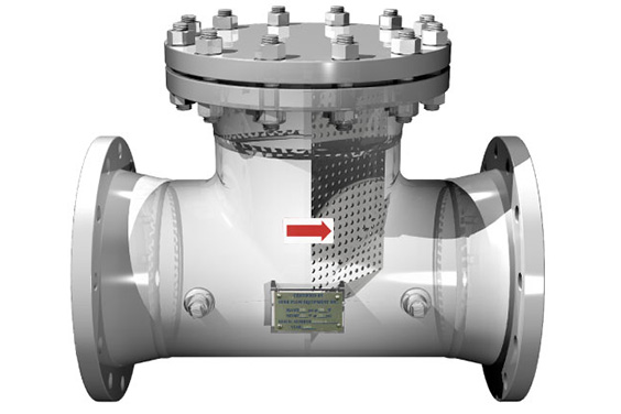
source: https://www.pinterest.com/pin/33003009756881044/
While setting up a process plant, the people involved in the installation refer to the piping and instrumentation diagram. This diagram is mainly used when planning the flow of the process. The process flow diagram (PFD) comes before the P&ID. The PDF shows how the functional equipment will fully work after the installation.
The PDF does not include detailed data or figures of specific measurements. It is only used as reference documentation when drawing a piping and instrumentation diagram. The piping and instrumentation diagram will provide the specifics of the workflow, for example, the piping system. This article will guide you on the P&ID valve Symbols.
Table of Contents
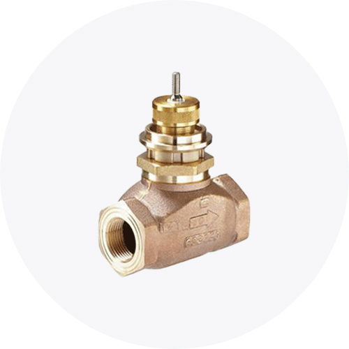
What does Piping & Instrumentation Diagram (P& ID) Imply?
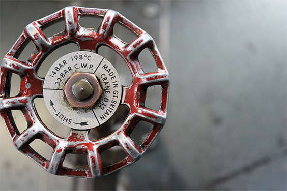
source: https://www.pinterest.com/pin/134193263886918948/
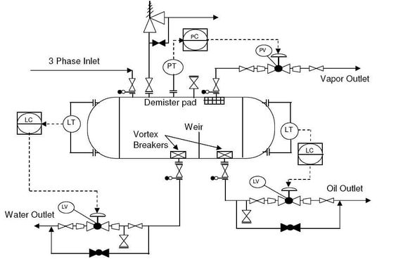
P&ID refers to a very detailed visual representation of all the components involved in the process flow. They include the vessels, piping, control valves, instrumentation, equipment, and other components involved in the plant process. The piping and instrumentation diagram is a very critical illustration of the stages of the plant process system.
The P&ID should not be used as maps or plans because the symbols used are not drawn to scale. When trying to understand the piping and instrumentation diagram, it is very crucial to know how to distinguish different symbols used in the diagram and what they represent in particular.
The piping and instrumentation diagram can be created using the software. You need to come up with a list of equipment and thoroughly check. Use the symbols that are within the library after the checking. You can then connect the checked equipment with pipes and go through those details with another person that you trust. Check it severally in order to identify any inefficiencies. Finish by sharing the piping and instrumentation diagram with your collaborators.
Features Of Piping And Instrumentation Diagram
The piping and instrumentation diagram has the following list of items in it.
- The process piping, identification, and sizes. The piping requirements like the special insulation and slope are indicated on the piping and instrumentation diagram.
- The mechanical equipment has numbers and names. They have to be indicated with their reference tag numbers, design data, type, and spares. They include tanks, heat exchangers, pumps, vessels, and columns
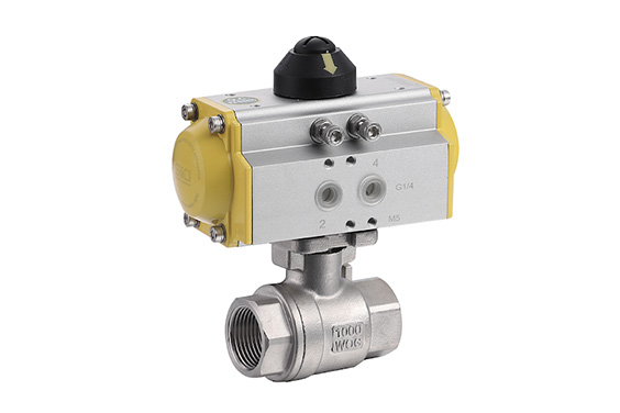
- Valves with their identification. There are manually operated piping valves that indicate their types for example check valves, gate valves, and ball valves. There are also automated valves e.g control valves, shut down valves, and blowdown valves. They are indicated with their size. Fail open and fail close are indicated on each valve. Finally, we have the safety valves which include the pressure, temperature, and relief center.
- The miscellaneous includes the Vents, fittings, drains, increasers, reducers, swaggers, and sampling lines. Drains and vents are indicated using symbols with their specific type and size. Piping fittings include the flanges, reducers, spacers, strainers together with their sizes.
- Flush lines and permanent startup. The lines should have their reference tag numbers, the class of the piping material, the size of the lines, fluid service, type of insulation, and thickness.
- Flow directions
- Interconnection references. They are indicated between piping OPC and instrument OPC. They are usually indicated with unique tag numbers.
- Control output and input, and the interlocks
- Interfaces for class changes
- Computer control system input
- Identification of subsystems and components that are delivered in the process.
- Quality level
- Seismic category
- Contractor and vendor interfaces.
Advantages Of Piping And Instrumentation Diagram
- The piping and instrumentation diagram is very useful in planning and implementing systems of safety control in different plants.
- The piping and instrumentation diagram that is prepared effectively enables the involved personnel to evaluate the process of construction nearly accurately.
- The piping and instrumentation diagram is very crucial when forming a steady foundation for any control program.
- The piping and instrumentation diagram acts as a symbolic language used by designers from the whole world to communicate among themselves and share what they consider important in the automated industries.
- The piping and instrumentation diagram helps in understanding the different conditions of designs in any engineering plant.
- The piping and instrumentation diagram is also crucial in operating, modifying, and trying to maintain the system process more efficiently.
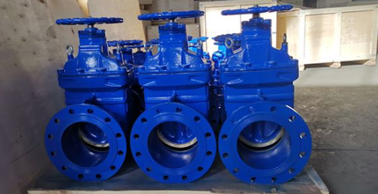
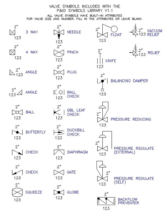
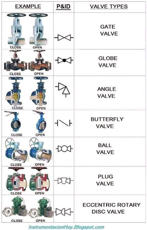
Common Valve Symbols In Piping And Instrumentation Diagram
Source: https://www.pinterest.com/pin/289074869838935561/
There are various valves used in the piping process, chemical, water distribution systems, marine, and other industrial applications. Each of these valves has its own symbol. At times it can be a bit hard to remember those specific symbols, but with regular practice, it becomes easier. Knowing the valve symbols is essential for you to understand the piping and instrumentation diagram.
We have two main types of valve symbols used in the P&ID. They include the valve symbol with modifier and the generic valve symbols. The valve symbols with a modifier will tell you about the exact valve type used in the pipeline. The Generic Valve Symbols in the P&ID can tell you if there is a valve present in the line, but it cannot tell the exact valve type.
Under the valve symbols, we also have 2 way on/off valves. This valve is symbolized by two equilateral triangles pointing towards each other. The valves use a different variety of lines to represent the various types of valves. The flow direction is indicated by arrowheads at the end of the lines. The most common 2-way valves include gate valves, butterfly valves, ball valves, plug valves, globe valves, pinch valves, needle valves, and diaphragm valves. Let us have a quick look through each of them briefly.
Ball Valve Symbols

source: https://www.pinterest.com/pin/566398090610356038/
The ball valve has two piping and instrumentation diagram symbols. This is because the isometric drawing and the P&ID symbols vary from one company to the other. You should note this is in case you want to switch companies. The piping and instrumentation diagram of ball valves has a solid center that is in a circular shape.
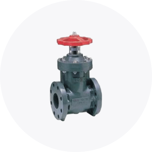
Gate Valve Symbols

Source: Google
The piping and instrumentation diagram (P& ID) symbol of the gate valve is achieved by the insertion of a vertical line in between two triangles. The gate valve system is just a modification of the generic valve symbols.
Globe Valve Symbols

source: https://www.pinterest.com/pin/423619908680831312/
The piping and instrumentation diagram symbol of the globe valves is obtained by modifying the generic valve symbol. A small dark circle is added in between the two triangles.
Relief Valve Symbols
Source: Google
Piping Instrumentation Diagram symbol of the relief valve symbols has a tank line port at the central part of it and arrowheads that point in the same direction. The relief valves are mostly used in the protection of the piping system from any cases of overpressure.
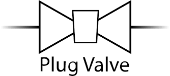
Plug Valve Symbol
Source: Google
The piping and instrumentation diagram symbol of the plug valve is obtained by having a diamond shape in between the two triangles. The plug valve directs the flow by simply using a linear motion to move a conically shaped plug inside the valve body.
Butterfly Valve Symbol

Source: Google
The piping and instrumentation diagram symbol of the butterfly valve symbol is a vertical line with a dot at the center. The butterfly valve symbol is the only symbol from the other valve symbols where a full triangle is not used.
Needle Valve Symbol

The piping and instrumentation diagram symbol of the needle valve is obtained by using a bowtie symbol with an arrow that is downward-pointing being at the center. It has a 2-way valve symbol with an arrow showing it is a needle valve. It also has multiple piping and instrumentation diagram symbols like in the case of ball valves.
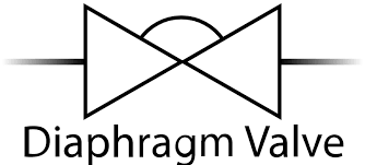
Diaphragm Valve Symbol
Source: Google
The piping and instrumentation diagram for the diaphragm valves is obtained by drawing a bow tie and a straight horizontal line through its center. Finish by erasing the top half. The remaining structure is what is referred to as the diaphragm call symbol. Most of the valve symbols are of the flange type. They mainly handle solid particles with process media.
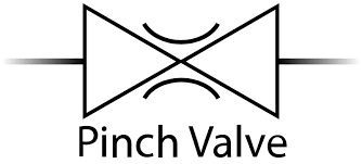
Pinch Valve Symbol
Source: Google
The piping and instrumentation diagram of pinch valves is obtained by drawing a bow tie and a straight horizontal line through its center, erase the line that will be visible inside the bow tie shape. Finish by drawing two unfinished circles on the top and bottom parts. The final structure is what we referred to as the pinch valve.
Conclusion
It is crucial to note that the main role of piping and instrumentation diagrams is to illustrate types of machinery and pipes. A separate chart should always be created when there is a need to elaborate a particular section of the piping and instrumentation diagram. The piping and instrumentation diagram goes hand in hand with the PFD.
Understanding the different symbols and what they represent in the piping and instrumentation diagram is very essential. Always use this diagram in all the construction processes for a proper guide, especially in engineering plants. This diagram should act as your starting point since every type of valve is well explained in detail.