Control Valves
Products Portfolio
By Type
By Design
By Material
By Actuator
By Industries
- Slurry Valves
- Water Treatment & Wastewater Valves
- Natural Gas Valve
- Chemical&Petrochemical
- Geothermal Energy
- Gas Process & Refinery
- Pulp and Paper Valves
- Mining Valves
Assessories
Control Valves
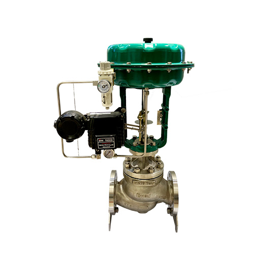
SIO produces quality control valves that will help you with your water handling system. A control valve system is made up of an actuator, valve body, positioner, and accessories. It is designed to allow fluid flow, endure static and differential pressure, and support seating exteriors.
Control valves will regulate the flow rate of fluid as the positioning of the valve disk or plug is altered by the actuator. They are useful in controlling a fluctuating process as close to the ideal set point as possible. Controller set points are usually pressure, temperature, and flow rate. Product restrictions, such as liquid level, density, and concentration, are also maintained by control valves.
You can trust SIO to offer you the best control valves to promote a smooth fluid flow for your applications.
Control Valve Manufacturer
Also known as a modulating valve, a control valve is a power-operated device used to control media flow or pressure rate in a system. It regulates flow at various degrees from minimum flow to full capacity. A control valve operates by responding to a signal from the control center.
A control valve is equipped with an actuator that can alter the position of the closing mechanism of the valve. It controls media flow through the movement of its disc or plug according to the opening(s) within its body. The valve disc or plug is connected to a stem, which is attached to an actuator.
An actuator controls the stem movement as instructed by the control device. It responds to a signal that typically comes from an external controller. The control valve and controller makes up a control loop.
Control Valve Features
Material
The control valves are accessible in different materials, including stainless steel, carbon steel, low temperature carbon steel, duplex, super duplex, and Inconel.
Temperature control range
The temperature control valves can withstand severe temperatures of about 2,100 degrees Fahrenheit.
Manufacturing and design criteria
The industrial control valves usually follow various design and manufacturing standards, such as API 6D, ASMEB16.34, and BS EN ISO 17292.
Pressure tests
Control valves follow different pressure test standards in order to stay durable. They include BS EN 12266 -1 & 2, API 6D, and API 598.
Benefits Of Using Control Valve
Easy Installation
One primary yet undeniable advantage of control valves is that they support easy installation. It allows you to save a significant amount of effort and time.
Automatic Operations
Another advantage is that control valves can be regulated automatically. It eliminates the reliance on the operator to unlock and shut down the valve.
Deter Clogging
The design of control valves are constructed in a manner that does not hinder the flow of fluids. Due to that, they do not barricade.
Eco-friendly
By using control valves, trashing the natural resources is curtailed extensively. It assists them to fulfill universal eco standards and makes them environmentally safe.
Budget Friendly Solution
It is possible to accomplish water conservation by employing control valves. They assist in saving a substantial expense on the water and seamstress costs for massive industries.
Standard and specification of Control Valves
Make sure to keep in mind the following aspects while planning to acquire control valves.
Materials
The body of control valves is of carbon steel (WCB) and stainless steel (CF8M).
Maximum differential closing pressure
The closing pressure of control valves differs based on the available options and models.
Bonnet And Trim
It is easy to peel out bolt-on bonnet to have easy entry to trim for examination and improvement. The control valves feature SS, RPTFE, or PEEK.
Design Features
The SIO control valves come with a plug that is robust, reliable, and the seat structure assures a rigid seal.
Bearings
They arrive with considerable bearings and shafts to deal with elevated pressure drops.
Type of End connections
The SIO control valves have flange end connections. The 150# Flange has 1/2″ to 4″ and 300# Flange retains 1/2″ to 4″.
Common Ball Valve Applications
There are different control valve applications that cater to several industries. Here is a brief list.
Control Valves For Steam Service
Compressor anti-surge systems
Control Valves For Gas Service
Liquefied petroleum gas
Hydraulic oils
Control Valves For High Temperature Service
Hot and cold water applications
Control Valves For Vacuum Service
Hydrocarbon processing
Liquefied natural gas
Control Valves For High Pressure Service
Pump stations
Manufacturing plants
Source Control Valves From China
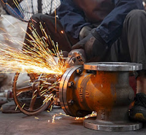
Do you want to acquire the best quality, durable, functional, and affordable control valves from a Chinese manufacturer? In that case, it is best to choose SIO. Our company has a large manufacturing plant where the valves are produced.
All the manufactured products meet the essential quality, durability, high-pressure standards. In addition to that, they also passed fire test standards and can operate for a long time. We supply the raw materials used to make the control valves.
What Are the Different Types of Ball Valves?
Control valves are available in different types with different designs, materials, accessories, etc in SIO. This is why it can be challenging to choose which control valve is suitable for your application. It is essentially important that you make an informed decision. Choosing the incorrect valve could lead to serious problems for the entire system.
To guide you, we have categorized control valves in different groups. This is to help you choose properly and prevent system problems as much as possible.
Control Valve Types by Actuation

Electric Control Valves
The electric actuator control valve models utilize a power source to work. It is possible to mount them, and they will change to the required location via the power source. These actuators are of two kinds: linear type and rotary type.
Pneumatic Control Valves
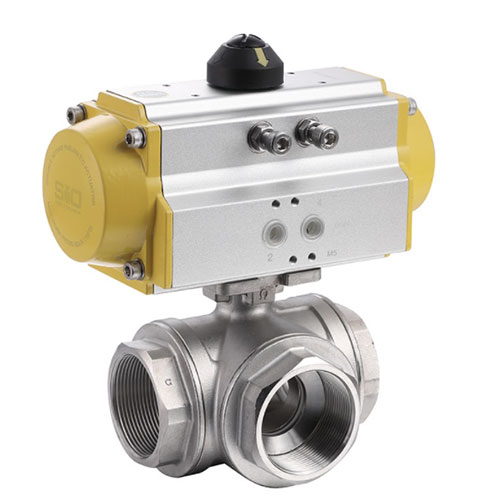
The pneumatic actuators are primarily utilized to transform the power of compressed air into motorized power to accomplish the essential task. They are ideal for industrial applications and projects that are associated with severe temperatures.
Solenoid Valve
The solenoid control valves are switched on or shut off electrically in order to unlock or lock the flow process. In general, they are utilized to regulate the direction of flow of fluid or air in pneumatic and hydraulic systems.
Servo Motor
The servo motors retain a closed loop that gives an ultimate performance at improved speeds. They are featured with high-precision screws and anti-backlash mechanics which provide accuracy.
Step Motor
A step motor employs gears with special additions in 90 degrees rotation between the range of 5,000 and 10,000 for detailed positioning at short speeds.
Diaphragm Actuator
The diaphragm actuators have compressed air executed to an adjustable disc, generally recognized as the diaphragm. These actuators can be reverse-acting or direct-acting.
Piston Actuator
The piston actuators are utilized when the push is restricted or when the actuator's hit is too low. These actuators are single-acting or double-acting.
Control Valves By Media Type
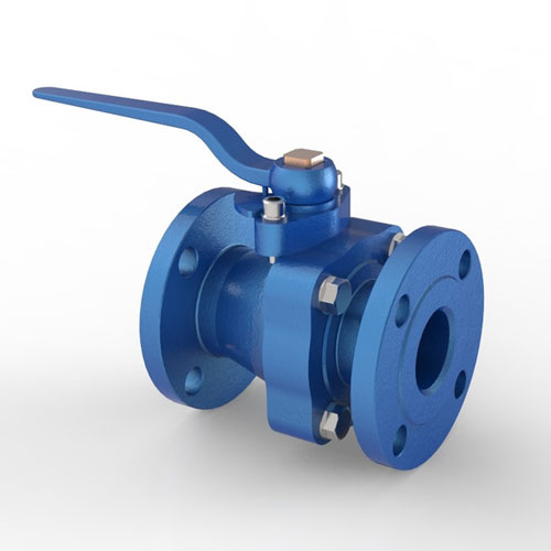
Water Control Valve
The water control valves are formulated to regulate various properties of water (hot water, ground water, cold water, potable water, salt water, or wastewater ).
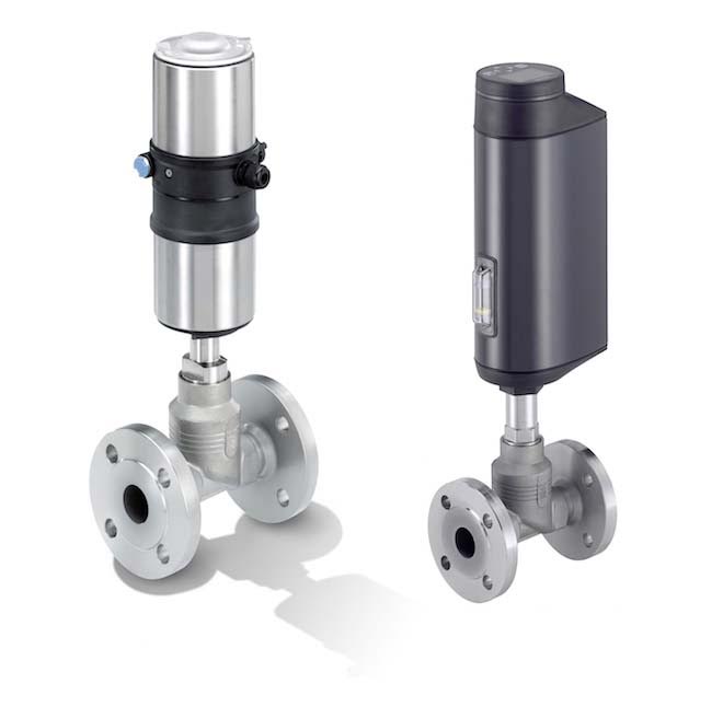
Steam Control Valve
The steam control valves are mainly utilized to regulate steam in several applications. The primary purpose of these control valves is to monitor the inlet steam pressure for procedure operations.
Control Valves by Application
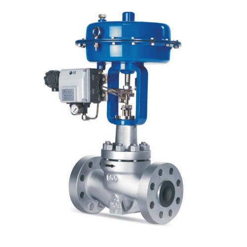
Two-way Control Valve
The two-way control valve implies the valve retains dual ports or entrances, which are an inlet port and an outlet port. These valves are utilized in a collection of industrial applications to deliver fundamental on and off services.
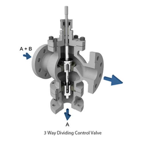
Three-Way Control Valve
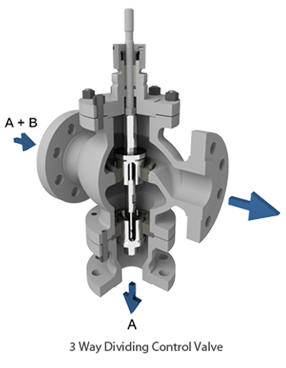
The three-way control valves have three ports. These valves are used in continual volume or flow pumping systems. They can work as diverting or mixing valves. The goal of these valves is to blend two liquids before they are sent to other containers or compartments.
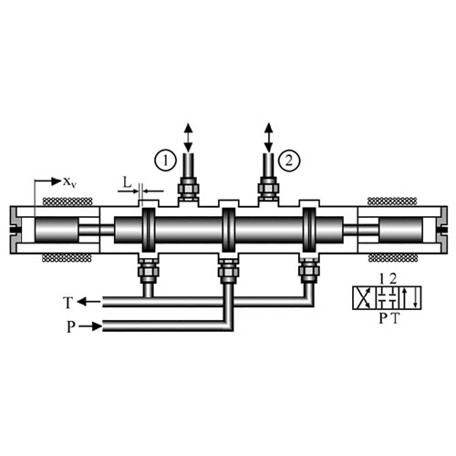
Four-way Control Valve
The four-way control valves come with four openings. They are primarily utilized for directional monitoring in pneumatic systems. These valves are suitable for industrial applications like clean air, natural gas, liquefied petroleum gas, and various liquid types.
Control Valves by Application
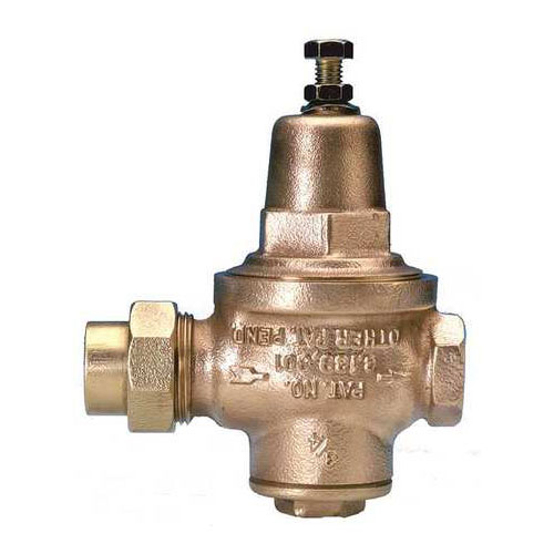
Pressure-reducing Valve
The pressure-reducing valves lessen a high inlet burden to a cured downstream pressure. It works without considering variations in supply and demand burdens. They enable liquid transmission at safe pressures and adequate levels in various operations.
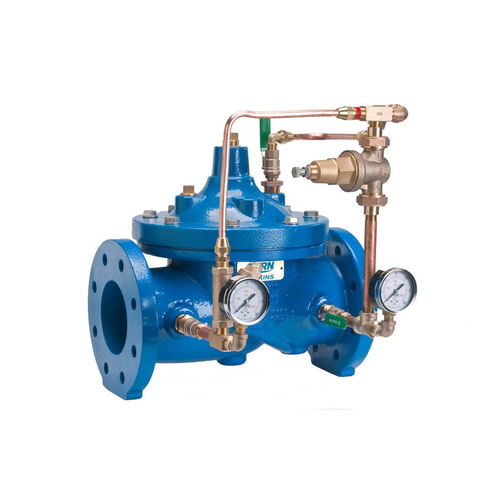
Pressure-relief Valve
The pressure-relief valves are utilized to alleviate additional pressure while regulating a downward upstream pressure. Their primary objective is to protect the whole system safely and deter severe disasters.
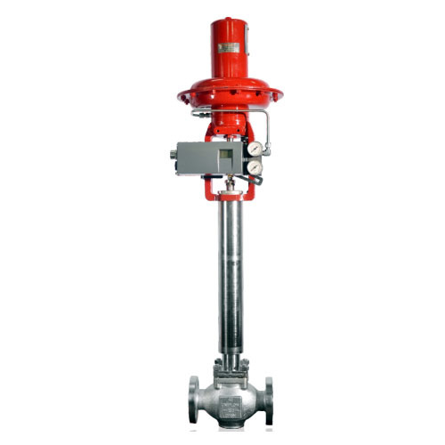
Cryogenic Control Valve
The cryogenic control valves are precisely constructed to deal with cryogenic services that have temperatures of -325 degrees Fahrenheit (-198 degrees Celsius). In general, they are prepared from stainless steel to resist drastic service circumstances.
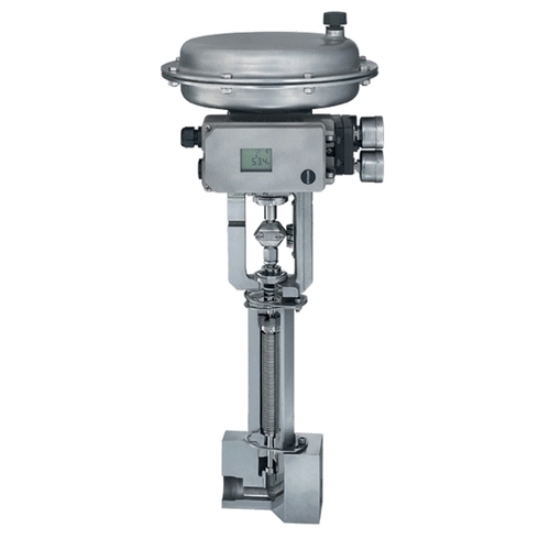
High-pressure Control Valve
The high pressure control valves are ideal for high-level projects dealing with elevated pressures and high temperatures. They arrive with a portable body to attain limited pressure loss. These valves also have a stabilizer to control disturbances surrounding the enclosure.
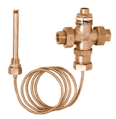
Temperature Control Valve
The temperature control valves can be utilized in two paths. They are suitable for blending hot liquid and cold liquid together in several quantities based on the provisions. In numerous situations, the cold liquid production is modified to alter the liquid temperature.
Control Valves by Flow Characteristics
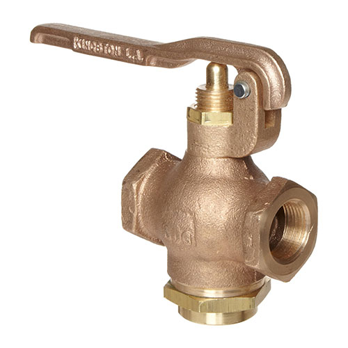
Quick Opening Control Valve
The quick opening control valves build a substantial boost in procedure flow for a limited initial modification in stem travel. Generally, they have a valve increase that is relatively high for modulation.
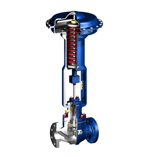
Linear Control Valve
The linear control valves have flow traits that give a linear relationship between the flow ratio and the place of the valve. In these valves, the flow path promptly depends on the posture of the stem.
Equal Percentage Control Valve
The equal percentage control valves feature flow aspects with a non-linear curve, in which the angle runs high as the valve unlocks. It implies the valve's flow capability largely boosts with the passage of the valve stem.
Control Valves by Material
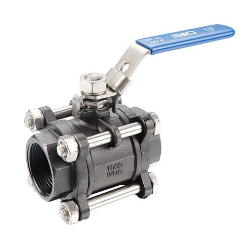
Carbon Steel Control Valves
The carbon steel valves are made of iron and carbon. These are more safe than stainless steel valves and highly resistant to wear, making them suitable for high pressure and extreme temperatures applications.
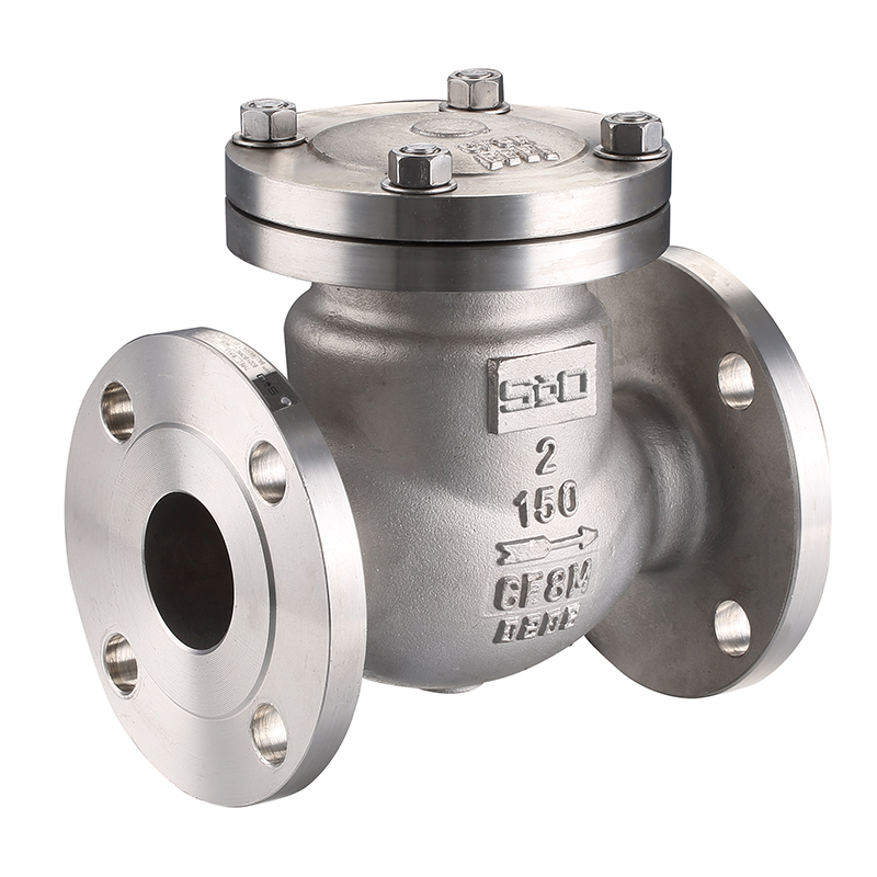
Stainless Steel Control Valves
There are control valves made of stainless steel substances. They are known for their high-end reliability and incredible resistance towards rust and corrosion. Due to that, they are ideal for every type of application.
Chrome-molybdenum Steel Control Valves
These valves can deal with higher pressures and temperatures. The material used is normally strong and reliable. These valves are used in condensate and high-pressure steam. They come with corrosion and rust resistance.
Valves Used as Control Valves
A control valve is available in various valve bodies that are made from different styles, sizes, connections, and materials. Choosing a control valve heavily relies on the application’s load characteristics, service conditions, and the task the valve performs.
Here are the valves that are commonly used as control valves:
Rotary Control Valves
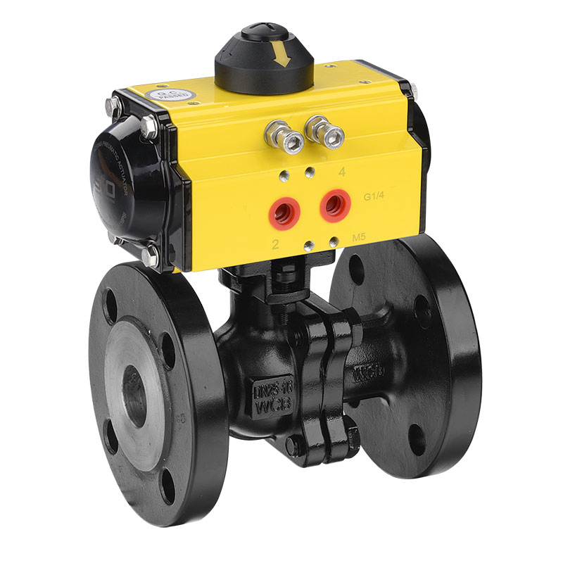
Ball Valve
A ball valve is a quick-acting rotary valve that provides a really tight shut-off. A standard ball valve complies with ASME face-to-face dimensions, which means this valve type is simple to modify and replace. Due to high flow capacity and low pressure drop, a ball valve is considered a high-recovery valve.
Butterfly Valve
A butterfly valve is made of a disc connected to a shaft, which is equipped with bearings to assist rotation. It is mainly used for basic throttling. Due to its design, a butterfly valve complies with ASME pressure ratings and face-to-face dimensions. This makes a butterfly valve simple to modify even when in line.
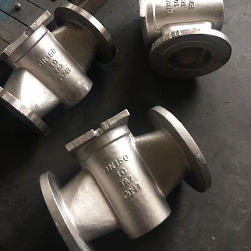
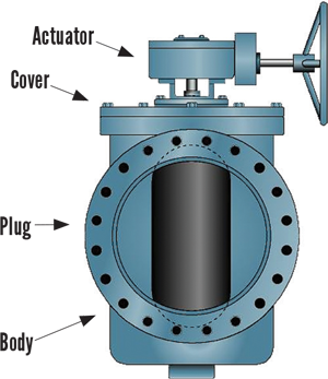
Eccentric Plug Valve
An eccentric plug valve is another type of rotary control valve equipped with a plug-shaped component that restricts media flow. This component observes an eccentric path when rotating. An eccentric plug valve is often used when handling crucial service conditions, such as erosive fluids and coking.
Linear Control Valves
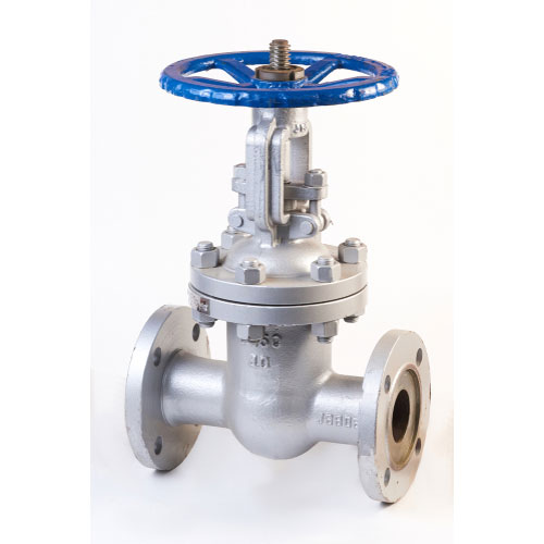
Gate Valve
A gate valve is a type of linear motion valve that is primarily used to fully permit or fully obstruct media flow. It uses a wedge-shaped disc as its closing element that ensures a tight sealing. A gate valve can cut through surface build-ups, scales, slurries, and other viscous fluids.
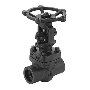
Globe Valve
A globe valve is made of a movable component and a fixed ring seat in a typical globular body. Globe valve is used for both throttling and shutting off flow passing through the globe valve. It is often used in applications that require accurate flow regulation and continued wide throttling.
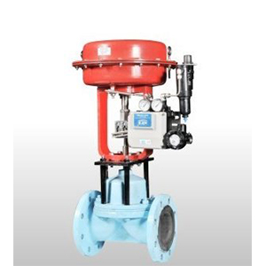
Diaphragm Valve
A diaphragm valve has earned its name from its flexible disc that comes into contact with the valve seat above the body to achieve a seal. Commonly known as the diaphragm, the flexible disc is pressure-responsive that sends force to control, close, or open the valve.
Control Valve Manufacturer
Also known as a modulating valve, a control valve is a power-operated device used to control media flow or pressure rate in a system. It regulates flow at various degrees from minimum flow to full capacity. A control valve operates by responding to a signal from the control center.
A control valve is equipped with an actuator that can alter the position of the closing mechanism of the valve. It controls media flow through the movement of its disc or plug according to the opening(s) within its body. The valve disc or plug is connected to a stem, which is attached to an actuator.
An actuator controls the stem movement as instructed by the control device. It responds to a signal that typically comes from an external controller. The control valve and controller makes up a control loop.

Factors to Consider When Choosing Control Valves
There are many types of control valves, all of which have their own strengths and limitations. Determining which control valve is suitable for your application relies on the specific functions they need to perform such as:
A control loop is made of a controller, sensing component, and a control valve. A sensing component is responsible for transmitting signals to a DCS (distributed control system) or a single controller.
The controller examines the setpoint and signal, and will make necessary adjustments through transmitting a signal to the valve. The adjustment is confirmed by the sensing component. Thus, completing the control loop.
An effective control valve must achieve the following:
• A wider rangeability, meaning it must be able to function over different flows;
• Display minimum hysteresis or dead time;
• React to signals within its operational range accurately;
• React with the needed stroking speed;
• Respond to additional adjustments properly
For a tighter control, a positioner could be added. This device improves the performance of the valve by enhancing the signal of the controller. Therefore, a more accurate response is achieved. Also, this helps in controlling the effects of any friction between the valve and stem, achieving a better sealing.
The quality of a control valve can be measured in terms of time constant, dead-time lag, and its gain. Among these three factors, the gain is the most significant.
Selecting materials must include the trim, hard body, seal and packing, and soft gasket materials. As a basic requirement, the trim and body must be suitable for the materials of the connecting pipeline.
Apart from cost considerations and client specifications, the properties of the fluid flow should also be considered. Also, take note whether or not the application is handling corrosive and erosive media. Hard-facing the internal parts of the valve with chromium-cobalt alloys or nickel may slow down erosion.
Moreover, high-temperature (>800°F) and low-temperature (below freezing point) applications must also be considered. For instance, at a high temperature, a control valve is exposed to increased leakage and stress as a result of internal parts expanding.
Fluids that rapidly go through the control valve could cool down to below zero temperatures. This condition is particularly true when controlling high-pressure hydrocarbon fluids. A flash computation should be done to inspect the outlet temperature in the lower pressure.
For other low-temperature applications, such as atmospheric moisture and cryogenic fluids, the moving parts of the control valve are subject to freezing, making them inoperable.
Therefore, a control valve used in such conditions need insulation. The body and packing must be made to endure high pressure. In applications having greater than 1,000 psi, graphite is used to assist soft packing to avoid extrusion in small openings.
Determining the system and flow properties will help select the right control valve. The specified maximum flow rate must have the proper design margin, which is usually 10%. In specifying the max flow rate, these characteristics must be considered: the system’s size, pipe schedule number, geometry, and construction materials.
Flow coefficient is the most essential factor in terms of measuring the size of a control valve. The calculation of flow coefficient relies on whether the process flow is compressible, incompressible, or mixed phase. There are formulas to determine these characteristics that allow proper measurement of the valve size.
The following are some factors that will help you decide which flow characteristic is suitable for your application:
Equal Percentage
• When the majority of the pressure drop of a control system is through the control valve;
• When the majority of the pressure drop of a control system is not through the control valve;
• When the pressure drop across the control valve is anticipated to stay constant;
• For pressure- and temperature-control linear loops; and
For flow-control or liquid-level services.
Fast Opening
For repeated on/off operation, such as semi-continuous services, or where a quick huge flow is needed, such deluge systems.
Bonnet
A bonnet is a part of a control valve that encloses the valve packing and actuator. A bonnet is usually designed to suit various ranges of temperature. Therefore, special considerations must be done when choosing the right bonnet for your control valve.
An extended bonnet is used for high temperatures, such as 450°F, and below freezing temperatures. This type of bonnet makes sure that the valve packing is away from crucial temperatures.
In cryogenic service, an extended bonnet isolates the stem-valve packing from the sub-zero flow. This prevents the packing from getting damaged.
Trim
A trim is made of the internal components of a control valve that come in contact with the process flow. The components that are not part of the trim are the bonnet, packing, and bottom gaskets and flanges.
A trim maintains a stable connection between the valve-plug lift and flow capacity. It also guarantees a positive shut-off of the control valve.
The seat is mainly responsible for achieving a tight shut-off. However, a tight shut-off and proper lift depend on other components of the control valve. These include actuator design, valve-stem packing, and shape of the valve body.
The preferred level of tight shut-off relies on the nature of the service. Measuring shut-off is based on the percentage of leaks in the flow when the control valve is in the closed position. There are different industry standards that specify the requirements for shut-off for a range of applications.
A typical standard that determines leakage classes is ANSI/FCI 70-2-1998 (3) or Control Valve Seat Leakage. These classes are between Class II (weak shut-off) to almost zero leakage (Class VI). Depending on the requirements of the application, the operator sets the TSO or tight shut-off requirement in one of the classes (in most cases, Class IV, V, or VI are chosen).
The selection of the valve trim is mainly based on the following: operation conditions of the fluid, basic flow characteristics for a specific trim (by the manufacturer), and the effects of various operating conditions at the basic flow characteristics. These factors indicate a trim’s flow characteristics that are used as reference when choosing the right trim.
A reduced trim helps in achieving accurate control of low flows and provides enough room for high flows in the near future. The design of this trim lessens the flow through the opening of the valve. However, there is increased precision in controlling flow due to the reduced distance between the plug and lift.
There is no rule that indicates a reduced-capacity trim must be used lower than a specific turndown rate. But when accurate control is needed at 20% to 25% valve capacity, a reduced trim may be an excellent solution.
The use of cages is common in trims as it provides several advantages:
- A cage may be designed to guarantee an equal distribution of fluid forces on the stem and plug. This design results to a balanced, cage-guided trim.
- A cage guides the plug to make sure that it is positioned properly and makes proper contact with the valve seat.
- A cage may be used to change the original flow characteristics of the control valve.
The stem and plug in a sliding-stem valve encounter pressures that may affect the control of the actuator. This could result to high dead-bands and improper stem movement. The fluid surrounding the stem can lift it up, either sideways or downward, and may even provide torsional pressure.
There are several trim designs that could balance and counteract these pressures. A balanced trim utilizes mechanical adjustments to the plug or a cage-guided trim to distribute and balance the pressure.
Noise
A control valve creates noise as a result of aerodynamic effects, mechanical vibrations, or cavitation. Unsteady flow, pressure oscillations, and high velocities generate vibrations that are typically below 100 dB (decibel). A decibel refers to the strength of sound at max level from a portable radio’s earphones.
Noise as a result of cavitation varies on its degree. An increase in pressure drop through a control valve increases noise. A control valve creates a rattling noise in full cavitation.
Once a type of valve and flow characteristics are determined, an initial size can be specified by calculating the stroke of the valve for every design flow.
A valve stroke refers to the ratio of the actual flow capacity to the computed flow capacity for a certain valve. Select a valve type that functions between 10% to 80% of the valve stroke through the anticipated operation range.
Guidelines When Choosing the Size and Type of Control Valve:
- Pressure drop distributed in a pumped circuit to a control valve must be equivalent to ⅓ of the dynamic losses in a process system at 15 psi or at a rated flow, whichever is higher.
- Pressure drop distributed in a control valve from a centrifugal compressor’s discharge or suction line must be 50% of the system’s dynamic losses or 5% of the actual suction pressure, whichever is higher.
- Pressure drop in a control valve in steam lines to process vessels, reboilers, and turbines must be 5 psi or 10% of the steam system’s actual pressure, whichever is higher.
- In an operation wherein static pressure transfers fluid from one pressure container to another, pressure drop distributed to a control valve must be 50% of the dynamic losses of the process system or 10% of the lower-terminal container pressure, whichever is higher.
- The gain on the valve must not be lower than 0.5.
- Do not use the above 90% and below 10% of the valve stroke. A valve is simpler to control when it is between 10% and 80%.
A control valve may need more maintenance when it is poorly designed as it cannot function properly under certain service conditions. Problems that could occur include wear of the seat, packing, actuator diaphragm, and valve body. The chances of these problems can be decreased by choosing the appropriate design and materials of the control valve.
For instance, a control valve that handles mixed liquids and solids should be cleaned frequently to get rid of dirt. In this situation, a globe valve might not be ideal as dirt could go through the stem seal. This could restrict control and potentially damage the valve. Instead, a rotary valve may be a more suitable choice.
Friction made between the valve stem and packing may cause wearing. A sliding stem usually causes more packing wear compared to a rotary stem. This is due to a sliding stem collecting deposits and may carry them through the valve packing.
For services that may cause erosion, a metal seat is preferred. If a soft seat is necessary, then it must be positioned in a way that it is protected from the flow path. If the seat and plug don’t have great contact, then it might be a good solution to lap the seat.
Lapping is only applicable to a metal seat. It is a process wherein the seat and plug are ground together manually so their surface finish match each other. This process can achieve a leak-free connection. Furthermore, selecting a control valve with distinguished features could help decrease maintenance.
Smart positioners and valves transmit unique parameters, such as stem travel and actuator pressure, to software. This software uses these parameters to compute performance indicators, like torque and stem-packing friction.
A reduced-port control valve is typically used than a full-port. This is because a reduced port generates a pressure drop that can achieve the proper flow capacity. Moreover, a reduced port is more affordable since it can fit a smaller valve body. Prevent from asking rare sizes of valves, such as 2.5, 3.5, and 22. These are difficult to find and may cost more compared to standard sizes.
A control valve can have different end connections. The most commonly used is the RF or raised face. An RTJ or ring-type joint is common in several high-pressure classes. A control valve may be welded to achieve a tight connection. Welding a valve into place removes the weight and expenses of using flanges. However, it may become an issue when the valve needs to be removed for maintenance or repair.
Valves Used as Control Valves
A control valve is available in various valve bodies that are made from different styles, sizes, connections, and materials. Choosing a control valve heavily relies on the application’s load characteristics, service conditions, and the task the valve performs.
Here are the valves that are commonly used as control valves:
Rotary Control Valves
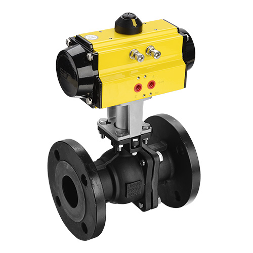
Ball Valve
A ball valve is a quick-acting rotary valve that provides a really tight shut-off. A standard ball valve complies with ASME face-to-face dimensions, which means this valve type is simple to modify and replace. Due to high flow capacity and low pressure drop, a ball valve is considered a high-recovery valve.
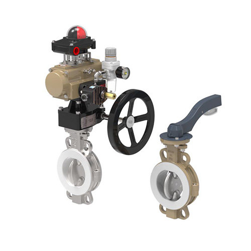
Butterfly Valve
A butterfly valve is made of a disc connected to a shaft, which is equipped with bearings to assist rotation. It is mainly used for basic throttling. Due to its design, a butterfly valve complies with ASME pressure ratings and face-to-face dimensions. This makes a butterfly valve simple to modify even when in line.
Source: Valve Magazine
Eccentric Plug Valve
A butterfly valve is made of a disc connected to a shaft, which is equipped with bearings to assist rotation. It is mainly used for basic throttling. Due to its design, a butterfly valve complies with ASME pressure ratings and face-to-face dimensions. This makes a butterfly valve simple to modify even when in line.
Linear Control Valves
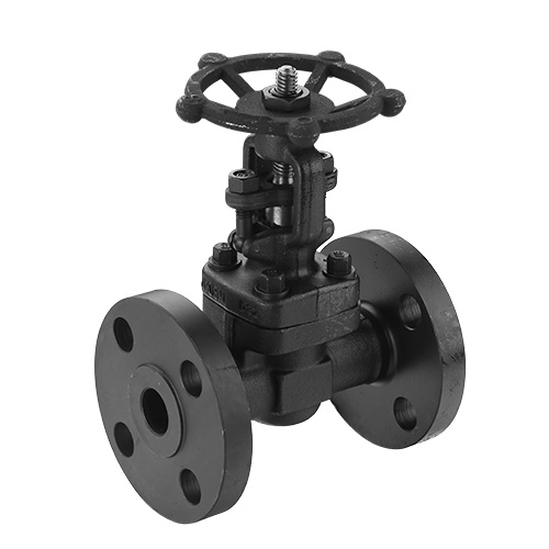
Gate Valve
A gate valve is a type of linear motion valve that is primarily used to fully permit or fully obstruct media flow. It uses a wedge-shaped disc as its closing element that ensures a tight sealing. A gate valve can cut through surface build-ups, scales, slurries, and other viscous fluids. Thus, a gate valve is ideal for handling air, gas, oil, steam, heavy fluids, non-condensing gases, corrosive and abrasive fluids.
The main advantage of a gate valve is it provides a full unobstructed flow, allowing a high flow capacity. Apart from slurries and other viscous fluids, a gate valve can allow rocks and other huge objects commonly found in mining operations to go through the gate valve safely.
Because of this feature, a gate valve is often found in mining industries, water and wastewater plants, processing plants, power plants, oil and gas industries, chemical processes, food and beverage industries, and more.
Globe Valve
A globe valve is made of a movable component and a fixed ring seat in a typical globular body. The stem moves the plug, which can be in a fully opened, semi opened, and fully closed position. It is used for both throttling and shutting off flow passing through the globe valve. The body and seat construction provides a globe valve excellent flow regulation properties.
A globe valve may come with several design options, including actuators, limit switches, positioners, and other essential accessories.
When a globe valve is fully opened, there is turbulent flow passing the plug and seat. This means a globe valve is well-fitted for applications wherein pressure drop is not a problem.
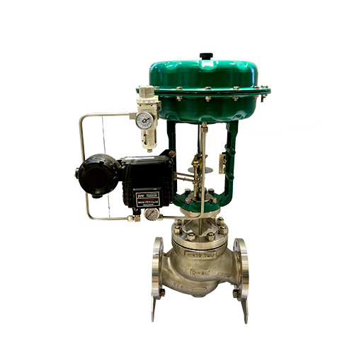
A globe valve can handle an array of fluids, such as vapors, liquids, and gases. It is also used when corrosive substances are involved. A globe valve is often used in applications that require accurate flow regulation and continued wide throttling services. It is also used in applications that have really high pressure drops.
Because of its accurate throttling, a globe valve is found in a wide range of industries, such as chemical and petrochemical, pulp and paper, power plants, and more.
Diaphragm Valve
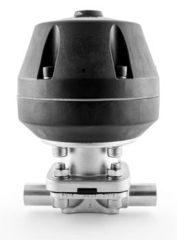
A diaphragm valve has earned its name from its flexible disc that comes into contact with the valve seat above the body to achieve a seal. Commonly known as the diaphragm, the flexible disc is pressure-responsive that sends force to control, close, or open the valve.
A diaphragm valve may come in either of its two basic types – the straight-through type or the weir type. The basic construction of both types are quite similar. However, they have significant differences for their bodies and diaphragms.
A straight-through diaphragm valve is used in services where the direction of flow changes within the process system. The bottom of the valve body is flat and is parallel to the media flow. This permits flow to move freely with no major blockages.
A weir diaphragm valve is the most used type and is ideal for general applications as well as abrasive and corrosive applications. It is also used to modulate minimum flows. The body of this valve type has an elevated lip that comes into contact with the diaphragm. This valve uses a smaller diaphragm as it is not required to stretch too much.
The Different Types of Control Valves
Control valves are available in different types with different designs, materials, accessories, etc. This is why it can be challenging to choose which control valve is suitable for your application. It is essentially important that you make an informed decision. Choosing the incorrect valve could lead to serious problems to the entire system.
To guide you, we have categorized control valves in different groups. This is to help you choose properly and prevent system problems as much as possible.
Control Valve Types by Actuation
Source: Indiamart
Electric Control Valve
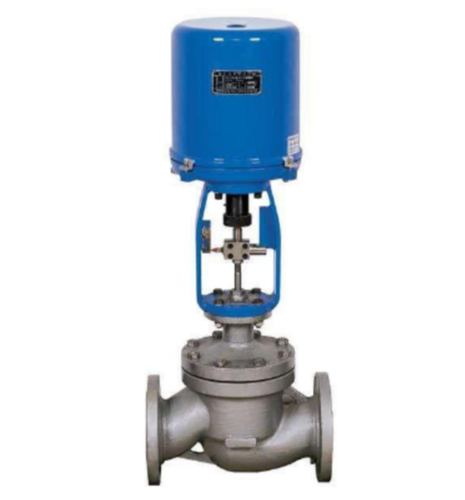
An electric control valve is operated through an electric actuator, which is a motor-driven device. It uses electric signal to create a motorized shaft rotation. In turn, this rotation is converted by the unit’s connection into linear motion, which allows the plug and stem to control flow.
In case of failure in the electric signal, this actuator may be adjusted to fail in its last, stem-in, or stem-out position. Among the widely used motors for an electric actuator are servo motors and step motors.
Servo Motor
A servo motor has a closed loop that provides optimal performance at increased speeds. It is equipped with anti-backlash mechanics and high-precision screws that give accuracies even to thousandths of an inch. However, this type of motor is more expensive compared to a step motor.
Step Motor
A step motor utilizes gears with special additions within the range between 5,000 and 10,000 at a 90-degree rotation for precise positioning at low speeds.
Brush DC and AC motors are used sometimes with limit switches when the accuracy of positioning is not that crucial. The motor is attached to a thread or gear that generates thrust to create valve movement. For valve protection, the torque-sensing mechanism of an electric actuator shuts the motor when it goes beyond the specified torque level.
Position switches are used as well to determine valve position. In many cases, a hand wheel and declutching mechanism are added for manual operation of the valve in case there is a power failure.
Pneumatic Control Valve
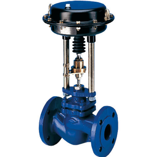
A pneumatic control valve operates through the use of a pneumatic actuator. This type of actuator uses compressed air signal from an outer control device to generate action. It is often available in two primary types – diaphragm actuators and piston actuators.
Source: Indiamart
Diaphragm Actuator
A diaphragm actuator has compressed air enforced to a flexible disc, commonly known as the diaphragm. This type of actuator is single-acting, meaning that air is provided to one side of the diaphragm only. A diaphragm actuator can either be direct-acting or reverse-acting.
- Direct-acting (spring-to-react)
In a direct-acting diaphragm actuator, the valve stem extends when diaphragm pressure increases. This mechanism closes the control valve, which is why it is sometimes called “air to close.” - Reverse-acting (spring-to-extend)
In a reverse-acting actuator, the valve stem is lifted when there is an increase in diaphragm pressure. In this case, the valve will open, which is why it is also referred to as “air to open.”
Piston Actuator
A piston actuator is commonly used in services when the thrust is limited or when the actuator’s stroke is too short. Compressed air is enforced to a piston enclosed in a durable cylinder. This type of actuator can be single-acting or double-acting.
A piston actuator can endure higher pressures and can provide small cylinder volumes that can act at an increased speed.
Source: Piping Engineering
Solenoid Valve
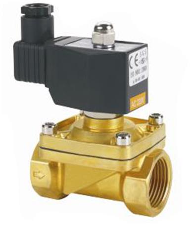
A solenoid valve is a type of control valve that is activated or deactivated electrically to open or close process flow. It is generally used to control the direction or flow of liquid or air in hydraulic and pneumatic systems.
Control Valve Types by Media Type

Source: Grabcad
Water Control Valve
A water control valve is designed to control different properties of water, such as cold water, hot water, ground water, salt water, potable water, or wastewater.
Steam Control Valve
As its name implies, a steam control valve is primarily used to control steam in various applications. The major function of this control valve is to control the inlet steam pressure for process operations. However, this valve may also be used to control temperature.

Source: Process Industry Informer
Control Valve Types by Number of Ports

Source: Indiamart
Two-way Control Valve
A two-way control valve means the valve has two ports or openings – an inlet port and an outlet port. These ports are generally indicated as A and AB. A two-way control valve is used in an array of industrial applications to provide basic on/off services. It may also be used for other complex services with the addition of special design features.
Three-Way Control Valve
A three-way control valve is a valve made with three ports that are labeled A, B, and AB. A control valve with three openings is often used in constant volume or flow pumping systems. It can either function as a diverting or mixing valve. This valve type can be installed at the return end or supply end of the pipe.
A diverting valve has one port on the supply end and two ports on the return end of the pipe. Meanwhile, a mixing valve has two ports on the supply end and one port on the returning end. The main purpose of this valve type is to mix two fluids before they are transmitted to another vessel or container.

Source: Indiamart
Source: Research Gate
Four-way Control Valve
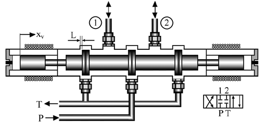
A four-way control valve has four openings that are equally spaced within the chamber of the valve. It is widely used for directional control in pneumatic systems. The plug, which may be a ball or plug (tapered or cylindrical), has two passages for connection of the adjacent openings.
This valve type is commonly found in various industrial applications that handle clean air, liquefied petroleum gas, natural gas, hydraulic oils, petroleum-based lubricants, and other types of fluids.
Control Valve Types by Application
Source: Zoro
Pressure-reducing Valve
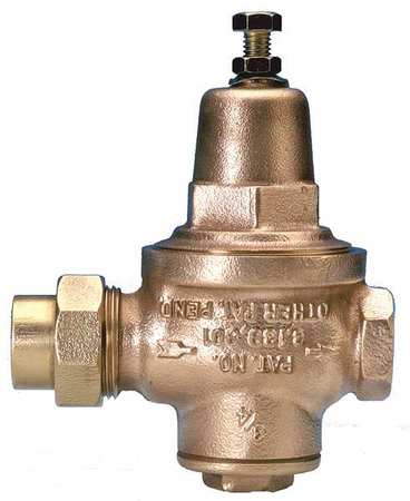
A pressure-reducing valve is a control valve that reduces a high inlet pressure to a fixed downstream pressure. This is regardless of the fluctuations in supply and demand pressures. It allows transmission of fluid at secure pressures and proper levels in different operations, such as irrigation systems, fire systems, and main feed lines.
A pressure-reducing valve is sometimes mistakes as a pressure-relief valve. There is actually a difference between the two. A pressure-relief valve is used to relieve the excess pressure of a system or vessel. It works only when pressure reaches a dangerous level. Meanwhile, a pressure-reducing valve is used to reduce the pressure in pneumatic and hydraulic circuits. It will reduce pressure even when there is only a small rise in the allowable pressure level.
Pressure-relief Valve
A pressure-relief valve is used to relieve extra pressure while controlling a low upstream pressure. It keeps downstream demand from compromising the upstream area. The main purpose of a pressure-relief valve is to keep the entire system safe to protect personnel and prevent serious accidents.
To ensure safety, a pressure relief valve protects the pressurized system or vessel when there is an overpressure event. An overpressure event is when pressure increases beyond the specified limit. This is done by setting the pressure-relief valve to open at a predetermined pressure level. It then closes back when the pressure of a system of vessel goes back to a safe level.
A pressure-relief valve is commonly used to protect in-line distribution pipes at pump stations.

Source: Home Depot

Source: Indiamart
Cryogenic Control Valve
A cryogenic control valve is specifically designed to handle cryogenic services with temperatures as low as -325°F (-198°C). This control valve is typically made from stainless steel to withstand severe service conditions. It is also equipped with an extended bonnet to make sure the stem-valve packing is secure from the extreme temperatures of process flow.
A cryogenic control valve is used to provide both on/off and throttling control of gases and liquids at very low temperatures. It is commonly employed in special operations in chemical industries and hydrocarbon processing, such as liquefied natural gas.
High-pressure Control Valve
A high-pressure control valve is made for heavy duty operations handling high pressures and temperatures. It generally comes with a compact body to achieve low pressure loss. It also comes with a stabilizer to regulate turbulence surrounding the cage. With these features, a high-pressure control valve permits a huge flow capacity and enhanced flow characteristics.
Since it is used in severe working conditions, a high-pressure control valve is made with durable materials. Most of the time, it is made from stainless steel due to the enhanced strength of the material. If budget is an important factor, a high-pressure control valve is usually made from chrome-molybdenum. It is also a durable material and less costly than stainless steel.

Source: Indiamart

Source: Toboa Energy
Temperature Control Valve
A temperature control valve is used in one of two ways. First, it may be used to mix hot fluid and cold fluid together in different amounts depending on the requirements. By raising the levels of hot or cold fluid, the operator can control the final temperature of the fluid. In many cases, the cold fluid output is adjusted to change the fluid temperature.
Second, a temperature control valve may work with a heat exchanger, which is a device that alters the temperature of process fluid by using cold or hot fluids. There is no direct contact between these fluids as they are encased in separate housing or pipes.
Control Valve by Flow Characteristics
Source: Galleon
Quick Opening Control Valve
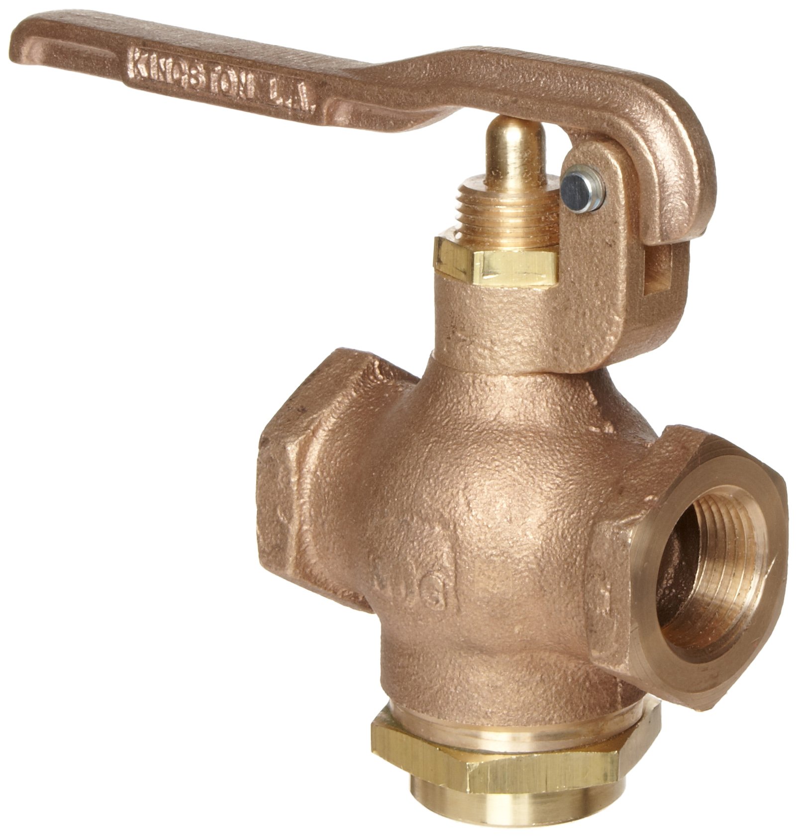
A quick opening control valve creates a significant increase in process flow for a minimal initial change in stem travel. Nearly a maximum flow is achieved at a low percentage of the highest stem lift. In general, it has a valve gain that is too high for modulation. Therefore, this type is used for on-off services, such as sequential operations in semi-continuous or batch processes.
Linear Control Valve
A linear control valve has flow characteristics that provide a linear connection between the flow rate and positioning of the valve. The flow path through a linear control valve directly relies on the position of the stem. This means that the flow follows a straight line, providing balanced volume changes to balanced lift changes.
A linear control valve is widely used in flow control services that need constant gain and level control of liquids.

Source: Crane Engineering
Equal Percentage Control Valve
An equal percentage control valve has flow characteristics with a non-linear curve, which the slope goes higher as the control valve opens. This means the valve’s flow capacity greatly increases with travel of the valve stem. The equal increments of travel create equal percentage changes in the current flow capacity.
Control Valve Types by Material
Carbon Steel Control Valve
Carbon steel is the most widely used body material for a control valve. It can handle almost any non-corrosive gases and liquids with temperatures up to 800°F for continuous operations or 1000°F for less frequent services. A carbon steel control valve is used in most steam and condensate applications.
Stainless Steel Control Valve
A stainless steel control valve is a durable type of valve. Stainless steel is known for its enhanced strength and excellent resistance to corrosion and abrasion. A stainless steel control valve is mainly designed for corrosive applications and services with high temperatures reaching 1000°F and up. It has better resistance to corrosion compared to other valve materials.
Chrome-molybdenum Steel Control Valve
Chrome-molybdenum is another widely used material for control valves. Better known as a chrome-moly steel, this material allows a control valve to handle higher pressures and temperatures than a valve made from carbon steel. Chrome-moly steel is generally stronger than carbon steel and in some cases, as durable as stainless steel.
A chrome-moly steel control valve is often employed in flashing condensate and high-pressure steam, both of which require erosion and corrosion resistance.
Contact Our Experts
Send us a message if you have any questions or request a quote.We Offer:
- A reply from our experts within 24 hours
- The latest detailed product catalugue
- One-stop service for your project
